

EMF electromagnetic flow meters are intended for fluid measurement in most industries including water, wastewater, food and beverage, pharmaceutical and chemical.
There are two basic components of electromagnetic flow meter: 1)The Detector, which includes the flow tube, isolating liner and measuring electrodes, and 2) The Converter, which is the electronic device responsible for signal processing, flow calculation, display and output signals.
The materials of construction of the wetted parts (liner and electrodes) should be appropriate for the specifications on the intended type of service. Review of the compatibilities consistent with the specifications is recommended.
All electromagnetic flow meters are factory tested and calibrated. A calibration certificate is included in the shipment of each meter.

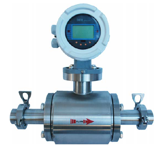
Insertion Type Electromagnetic flowmeter
Use Medium: Conductive Liquid
Fluid: Liquid with conductivity
Not for: Gas, Steam, Oil
Lot kinds of lining material to choose
Great resistance to causticity
No moving part
Less requirements on (straight pipe) meter run
Product Description
| Pipe Diameter | from DN150 to DN2000 |
| Velocity Range | 0.3 to 6.0 m/sec |
| Conductivity | bigger than 50 μS/cm |
| Flow Direction | direct and reverse |
| Operating Temperature | -30 to 90ºC |
| Operating Pressure | 20 bar maximum |
| Electric Connection | ½”NPT thread or ½” cable gland |
| Process Connection | thread BSP or others |
| Power Consumption | 5 W |
| Accuracy | ±1% of reading |
| Enclosure | IP67, IP68, diecast aluminum |
| Rod Material | 304 or 316 stainless steel |
| Electrodes | stainless steel 316L |
| Converter Mounting Type | remote CEV2000 compact with local PRO1000 |
| Installation Environment | Installation and removal with pressurized line |
| Pipe Size | DN 150 to DN 2000 |
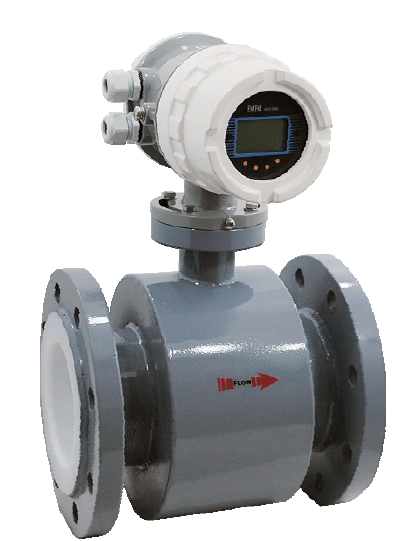
Electromagnetic flowmeter
Use medium:Conductive Liquid
Fluid: Liquid with conductivity
Not for: Gas, Steam, Oil
Lot kinds of lining material to choose
Great resistance to causticity
No moving part
Less requirements on (straight pipe) meter run
| Model | EMF-1 | EMF-2 | EMF-3 |
| Converter | Compact | Remote | Compact with Battery Power |
| Accuracy | 0.5% of Rate | 0.5% of Rate | 1.0% of Rate |
| Conductivity | >5μs/cm | >5μs/cm | >5μs/cm |
| Min. Velocity | 0.3 m/s | 0.3 m/s | 0.3 m/s |
| Max. Velocity | 10 m/s | 10 m/s | 10 m/s |
| Turndown Ration | Standard 1:20; Others on request | Standard 1:20; Others on request | Standard 1:20; Others on request |
| Output | 4-20mA/Pulse | 4-20mA/Pulse | Consult the factory |
| Power Supply | (1) 110-240Vac (2) 18-36 Vdc |
(1) 110-240Vac (2) 18-36 Vdc |
Lithium Battery |
| Communication | Optional: RS485; MODBUS; HART; Profibus-DP | Optional: RS485; MODBUS; HART; Profibus-DP | Optional: RS485; MODBUS; HART; Profibus-DP |
| Ex-Proof Level | Exd[ia]qIICT5 | Exd[ia]qIICT5 | Exd[ia]qIICT5 |
| Protection Level | IP65 | Converter: IP65 Sensor: IP65; (IP68 on request) |
IP65 |
| Diameter | DN10-DN1200 | DN10-DN1200 | DN10-DN1200 |
| Installation | 1. Flange (Standard: ISO; Optional: ANSI, DIN, JIS); 2. Thread (Standard: G; Optional: NPT); 3. Wafer |
||
| Pressure Rating | Standard: 1.6Mpa; Others on request | ||
| Fluid Temperature | Standard: PTFE: <120℃ (customized PTF)E: <120℃) ; Rubber: <60℃ |
||
| Ambient Temperature | -30℃-60℃ | -30℃-60℃ | -30℃-60℃ |
Measuring system
| Application range | Gas; Liquid; Steam | |
| Measured Value | ||
| Primary measured value | Flow Rate | |
| Secondary measured value | Volume flow ; (Pressure and Temperature is available for model with compensation) | |
Design
| Modular construction | The measurement system consists of a flow sensor and a signal converter. It is available as compact and as separate version. | |
| Compact version converter | N Type: Pulse output without local display A Type: 4‐20mA Output without local display B Type: Local Display; Lithium Battery Power; No Output (Battery Part No.: ER26500) C Type: Local Display; 24V DC Power; 4‐20mA Output; Optional Function: (1) Backup Power Supply: Lithium Battery (2) Modbus RS485 (3) Pulse Output |
|
| Connection | Flange: DN15‐DN300 Wafer: DN15‐DN300 |
|
| Measurement Ratio | Standard – 10:1 | |
Measuring accuracy
| Reference conditions | Flow conditions similar to EN 29104 Medium: Water / Gas Electrical conductivity: ≥ 300 μS/cm Temperature: +10...+30°C / +50...+86°F Inlet section: ≥ 10 DN Operating pressure: 1 bar / 14.5 psig |
|
| Flow Meter Accuracy | For Liquid: 1.0% of rate For Gas and Steam: 1.5% of rate Inse rtio ntyp e: 2.5% of rat e |
|
Operating conditions
| Reference conditions | ||
| Process temperature | T1 Level: ‐20...+70°C T2 Level: ‐20...+250°C T3 Level: ‐20...+350°C |
|
| Ambient temperature | Standard (with aluminum converter housing): ‐10…+55°C |
|
| Storage temperature | ‐20...+70° | |
| Pressure | ||
| EN 1092‐1 | DN200…DN300: PN10 DN100…DN200: PN 16 DN15…DN80: PN 25 Other pressures on request |
|
| ASME B16.5 | 1/2”...8": 150 lb RF Other pressures on request |
|
| JIS | 1/2”...8": 10 K Other pressures on request |
|
Installation conditions
| Installation | Take care that flow sensor is always fully filled For detailed information see chapter "Cautions for Installation" |
|
| Flow direction | Forward Arrow on flow sensor indicates flow direction. | |
| Inlet run | ≥ 10 DN | |
| Outlet run | ≥ 5 DN | |
Materials
| Sensor housing | SS304 | |
| Flanges | SS304 | |
| Converter Housing | Standard: polyurethane coated die‐cast aluminum | |
Process connections
| Flange | ||
| EN 1092‐1 | DN15...300 in PN 6...25 | |
| ASME | 1/2”…12" in 150 lb RF | |
| JIS | 1/2”…12” in 10...20K | |
| Design of gasket surface | RF | |
| Wafer | DN15…DN300 | |